

How To Draw Shear Force Diagram
This commodity is office of the solid mechanics course, aimed at engineering students. Delight leave feedback in the discussion section above.
What is shear force? [edit | edit source]
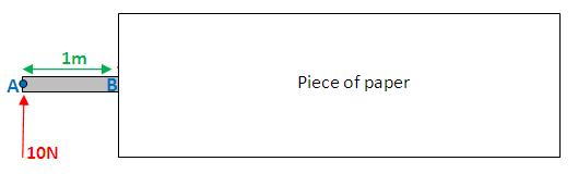
Beneath a strength of 10N is exerted at point A on a beam. This is an external forcefulness. However because the beam is a rigid construction, the force will be internally transferred all along the axle. This internal strength is known equally shear force. The shear force between point A and B is usually plotted on a shear force diagram. Equally the shear forcefulness is 10N all forth the axle, the plot is simply a straight line, in this example.

The idea of shear force might seem odd, maybe this instance will help clarify. Imagine pushing an object forth a kitchen table, with a 10N force. Even though you're applying the force only at one point on the object, it's not just that bespeak of the object that moves frontwards. The whole object moves forwards, which tells you lot that the force must take transferred all along the object, such that every atom of the object is experiencing this 10N force.
Delight notation that this is not the full explanation of what shear force actually is.
Basic shear diagram [edit | edit source]
What if there is more than 1 forcefulness, as shown in the diagram beneath, what would the shear force diagram wait similar then?

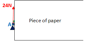
The way y'all go about this is past figuring out the shear force at points A,B,C,E (every bit in that location is an external force interim at these points). The mode you lot work out the shear forcefulness at any point, is by covering (either with your hand or a piece of paper), everything to correct of that signal, and simply calculation up the external forces. And then plot the indicate on the shear forcefulness diagram. For illustration purposes, this is done for point D:

Shear force at D = 10N - 20N + 40N = 30Newtons

Now, let'south practise this for point B. BUT - slight complication - in that location's a force interim at bespeak B, are you going to include it? The reply is both yes and no. You need to take 2 measurements. Firstly put your piece of paper, so information technology'south Merely before betoken B:
Shear force at B = 10N

Now place your paper Merely after point B:

Shear forcefulness at B = 10N - 20N = -10N
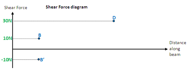
(B' is vertically below B)
Now, practice bespeak A, D and E, and finally join the points. your diagram should look similar the ane below. If yous don't understand why, leave a message on the discussion section of this page (its at the meridian), I will elaborate on the explanation:

Notice how nothing exciting happens at betoken D, which is why you wouldn't ordinarily analyse the shear force at that point. For clarity, when doing these diagrams it is recommended you move you paper from left to right, and hence analyse points A,B, C, and East, in that order. You tin besides do this procedure roofing the left side instead of the correct, your diagram volition be "upside down" though. Both diagrams are correct.
Basic angle moment diagram [edit | edit source]
Bending moment refers to the internal moment that causes something to bend. When yous bend a ruler, even though use the forces/moments at the ends of the ruler, bending occurs all along the ruler, which indicates that in that location is a bending moment acting all along the ruler. Hence angle moment is shown on a bending moment diagram. The aforementioned case from before will be used hither:
To work out the angle moment at any point, cover (with a piece of newspaper) everything to the right of that point, and have moments most that point. (I will accept clockwise moments to be positive). To illustrate, I shall work out the bending moment at indicate C:
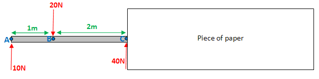
Bending moment at C = 10Nx3m - 20Nx2m = -10Nm
(Delight note that the two diagrams below should show units in "Nm", not in "North" as information technology is currently showing)
Detect that there's no need to work out the bending moment "merely earlier and just later on" point C, (equally in the example for the shear forcefulness diagram). This is because the 40N forcefulness at point C exerts no moment virtually point C, either way.
Repeating the procedure for points A,B and East, and joining all the points:

Normally you lot would expect the diagram to start and finish at zero, in this case it doesn't. This is my fault, and information technology happened because I accidentally chose my forces such that there is a moment disequilibrium. i.e. accept moments near whatsoever point (without covering the right of the betoken), and you lot'll notice that the moments aren't balanced, as they should be. It also ways that if you're covering the left side equally opposed to the correct, y'all will get a completely unlike diagram. Sorry about this... Upon inspection, the forces are unbalanced, then it is immediately expected that the diagram will most likely non be counterbalanced.
Signal moments [edit | edit source]
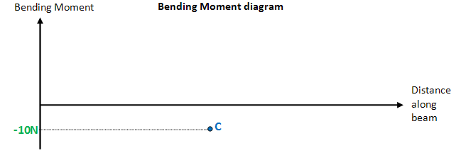
Indicate moments are something that you may not accept come beyond earlier. Below, a point moment of 20Nm is exerted at signal C. Work out the reaction of A and D:

Force equilibrium: R1 + Rtwo = 40
Taking moments virtually A (clockwise is positive): xl·2 - 20 - six·R2 = 0
R1 = 30N , Rii = 10N
If instead you were to accept moments nigh D you lot would get: - twenty - 40·four + half-dozen·R1 = 0
I think it'due south of import for you to see that wherever you take moments about, the point moment is always taken as a negative (because information technology'south a counter clockwise moment).
So how does a bespeak moment affect the shear force and angle moment diagrams?
Well. It has absolutely no effect on the shear force diagram. Yous can simply ignore point C when drawing the shear strength diagram. When drawing the angle moment diagram you will need to work out the angle moment simply earlier and just later bespeak C:

Just before: bending moment at C = 3·thirty - 1·twoscore = 50Nm
Just after: bending moment at C = 3·xxx - one·40 - 20 = 30Nm
And so piece of work out the bending moment at points A, B and D (no demand to exercise before and later for these points). And plot.
Cantilever beam
Until now, y'all may accept only dealt with "only supported beams" (similar in the diagram above), where a beam is supported past 2 pivots at either end. Below is a cantilever beam, which means - a beam that rigidly fastened to a wall. Only like a pivot, the wall is capable of exerting an upwardly reaction force Rone on the axle. Nevertheless information technology is also capable of exerting a signal moment M1 on the axle.

Force equilibrium: R1 = 10N
Taking moments about A: -Thousand1 + 10·2 = 0 → Mane = 20Nm
Uniformly Distributed Load (UDL) [edit | edit source]
Below is a brick lying on a axle. The weight of the brick is uniformly distributed on the beam (shown in diagram A). The brick has a weight of 5N per meter of brick (5N/k). Since the brick is 6 meters long the total weight of the brick is 30N. This is shown in diagram B. Diagram B is a simplification of diagram A. Equally you volition run into, you volition demand to be able to convert a blazon A diagram to a type B.

To make your life more difficult I have added an external force at point C, and a point moment to the diagram below. This is the near hard type of question I tin can think of, and I will do the shear force and angle moment diagram for information technology, step by step.

Firstly identify the key points at which you lot volition work out the shear force and bending moment at. These volition be points: A,B,C,D,East and F.
As you would take noticed when working out the bending moment and shear force at whatsoever given point, sometimes you but work information technology out at the point, and sometimes you piece of work it out merely before and afterward. Here is a summary: When drawing a shear strength diagram, if you are dealing with a point force (points A,C and F in the to a higher place diagram), work out the shear strength before and after the bespeak. Otherwise (for points B and D), just work it out right at that betoken. When drawing a bending moment diagram, if you are dealing with a point moment (point Due east), piece of work out the bending moment before and afterwards the point. Otherwise (for points A,B,C,D, and F), work out the bending moment at the point.
After identifying the cardinal points, you want to work out the values of R1 and Rii. You at present demand to convert to a type B diagram, as shown below. Discover the 30N force acts right in the middle between points B and D.

Force equilibrium: R1 + Rii = 50
Take moments almost A: 4·xxx + 5·20 + xl - 10·R2 = 0
Rone = 24N , Rii= 26N
Update original diagram:

Shear strength diagram [edit | edit source]
point A:

point B:

Notice that the uniformly distributed load has no effect on point B.
betoken C:
Just before C:

Now convert to a type B diagram. Full weight of brick from betoken B to C = 5x4 = 20N

Shear force before C: 24 - 20 = 4N

Shear force afterward C: 24 - 20 - 20 = -16N
bespeak D:

Shear force at D: 24 - xxx - 20 = -26N
signal F:
(I have already converted to a blazon B diagram, beneath)

Finally plot all the points on the shear force diagram and join them upwards:

Bending moment diagram [edit | edit source]
Signal A
Bending moment at A: 0Nm
Point B

Bending moment at B: 24·ane = 24Nm
indicate C:
(I take already converted to a type B diagram, below)
Bending moment at C: 24·five - xx·two = 80Nm
indicate D:
(I have already converted to a type B diagram, below)

Bending moment at D: 24·7 - 30·3 - 20·ii = 38Nm
point E:
(I have already converted to a type B diagram, below)

signal F:
(I have already converted to a type B diagram, below)

Angle moment at F: 24·10 - 30·6 - xx·5 + 40 = 0Nm
Finally, plot the points on the bending moment diagram. Join all the points up, EXCEPT those that are nether the uniformly distributed load (UDL), which are points B,C and D. As seen beneath, y'all demand to draw a curve between these points. Unless requested, I will not explain why this happens.

Note: The diagram is non at all fatigued to scale.
I take drawn ii curves. One from B to C, ane from C to D. Discover that each of these curves resembles some function of a negative parabola.
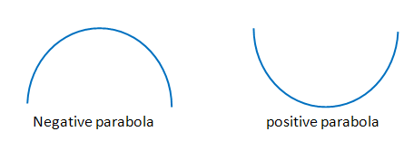
Dominion: When drawing a bending moment diagram, nether a UDL, you must connect the points with a curve. This curve must resemble some part of a negative parabola.
Note: The convention used throughout this folio is "clockwise moments are taken equally positive". If the convention was "counter-clockwise moments are taken as positive", you would demand to draw a positive parabola.
Hypothetical scenario [edit | edit source]
For a hypothetical question, what if points B, C and D, were plotted equally shown below. Notice how I have drawn the curves for this case.

If you wanted to find the peak of the bend, how would you do information technology? Simple. On the original diagram (used at the start of the question) add an additional betoken (signal G), centrally betwixt betoken B and C. Then piece of work out the angle moment at bespeak K.
That's it! If y'all have plant this article useful, please comment in the word section (at the pinnacle of the folio), equally this will assist me decide whether to write more manufactures like this. Also please comment if there are other topics yous want covered, or yous would like something in this article to be written more conspicuously.
Back to the solid mechanics course
Taltastic fourteen:11, fifteen September 2022 (UTC)
External Links [edit | edit source]
- FREE Online Shear Force and Bending Moment Diagram (SFD & BMD) Computer.
- Tutorial on how to depict bending moment diagrams
- Free Figurer for Calculations of shear strength and bending moment

Source: https://en.wikiversity.org/wiki/Shear_Force_and_Bending_Moment_Diagrams
Posted by: torresthereenewhe.blogspot.com
0 Response to "How To Draw Shear Force Diagram"
Post a Comment